Right, now I have decided on my product I need to purchase the keypad kit, put it together and make my alterations.
The kit comes from a company called Tech Supplies (http://www.techsupplies.co.uk/epages/Store.sf/en_GB/?ObjectPath=/Shops/Store.TechSupplies/Products/CHI008) and contains the basics I need for making my safe.
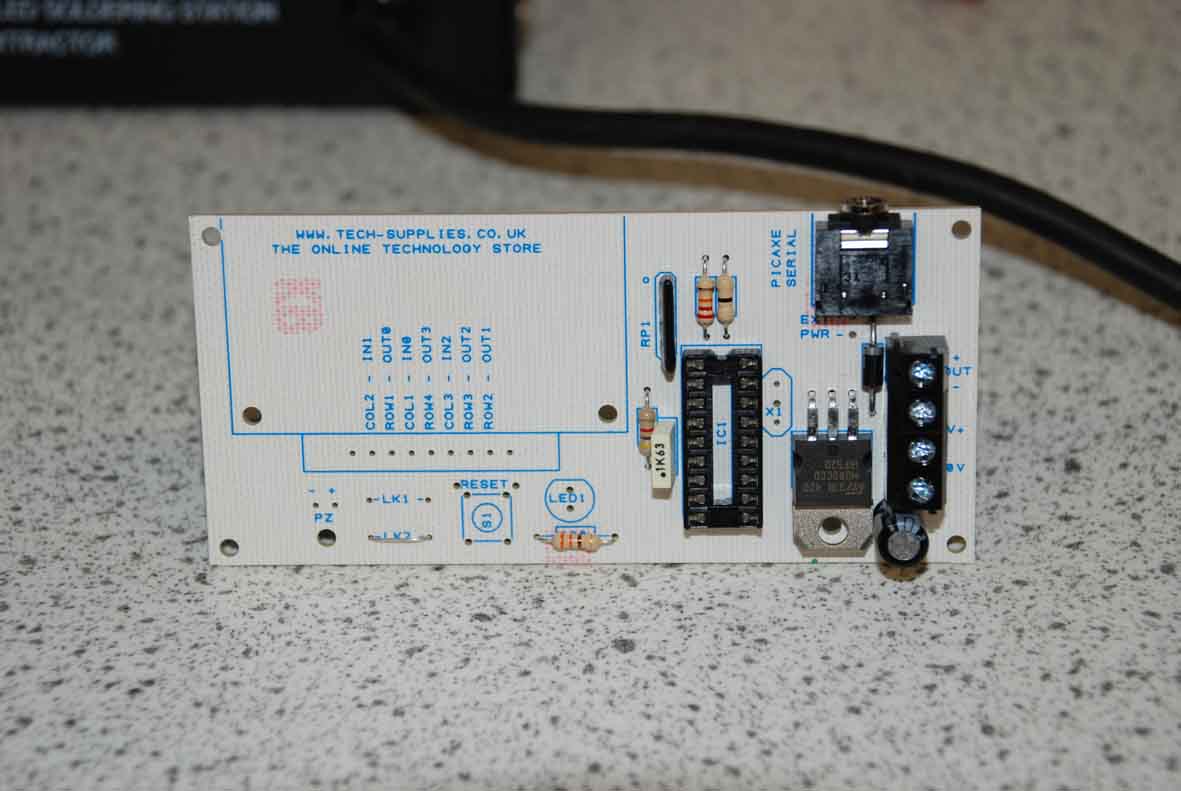
Before I received my kit I had assumed that the keypad would work by assigning an input to each number on the pad so the microcontroller would know which buttons had been pressed, this would take up the majority of pins on my 18 pin chip leaving very few to use for outputs such as lights and sounds. On arrival I found that the microcontoller used a surprisingly simple method of scanning that reduced the number of pins needed to 7. It manages this by breaking the pad up into 3 columns and 4 rows, assigning the columns to inputs and the rows to outputs. If all the outputs (rows) are switched off the signal to the microcontroller along the inputs is 0-0-0. if a button is pressed while the rows are switched off the signal remains 0-0-0, however if you switch one of the rows high and press a button in that row for example 1 the signal to the microcoltroller will be 1-0-0 telling it that button 1 has been pressed. if the signal had been 0-1-0 it would tell the microcoltroller that button 2 had been pressed. The PIC scans the keypad by continuously switching each of the output rows high in turn, waiting for an input signal back corresponding to the button pressed. The full description of the workings of the kit can be found here chi008.
In putting it together I knew that I would need to reposition elements such as the LED and the keypad itself so I soldered it together using flying leads:
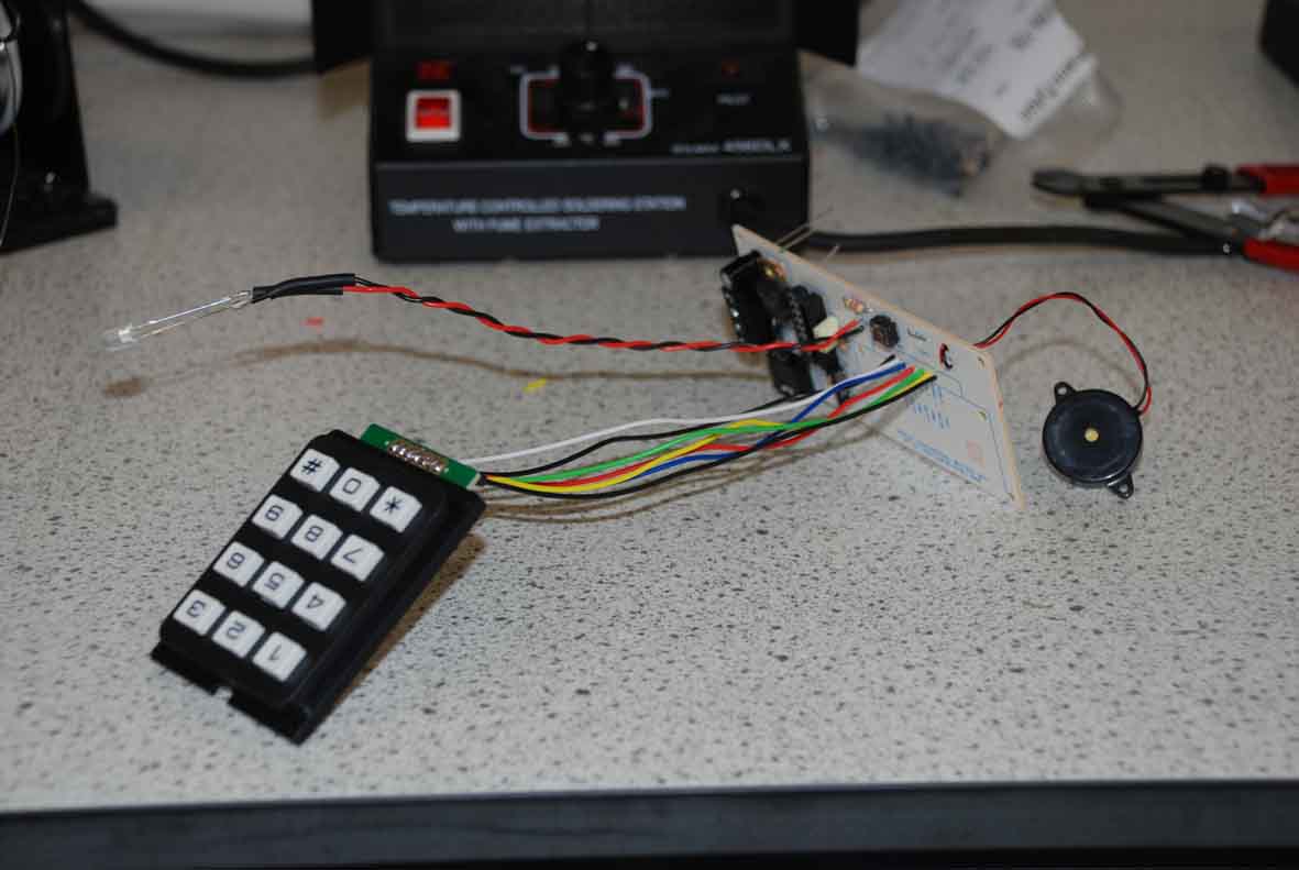
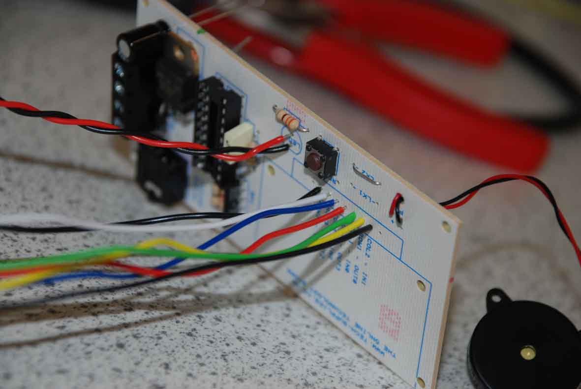
This means that I can easily fit the components into my case design and shorten/neaten the wires as required.
Time to test… (connects up battery pack with eyes squinched shut in anticipation of failure) It Works!! The bi-colour LED glows red to show that the circuit is in it’s locked position, as the code is entered the buzzer sounds for each button press and once the correct code is used the bi-colour LED changes to green and the output for the solenoid (just a connector block at the moment) registers a 4.5v signal when measured with a multi meter then resets after 5 seconds. So I have a working circuit, now all I need is to create my case, connect up a solenoid for my locking mechanism, add in any additional lights and sounds, re-programe my chip and test it all over again (not much to do then…).