To design a strong case that will be simple to construct I need to do some research on joining acrylic, hinges and other components
Glues:
Solvent Cement: As I have used in the past I could use a solvent cement to join the acrylic components. This glue works via capillary action so the edges to be joined must fit together perfectly, it shouldn’t be difficult to get perfect edges using the laser cutter but I don’t think this join will be strong enough for the safe.
Araldite: This would give a strong joint with edges that may not fit together exactly, it can fill small gaps. Hmmm on testing it’s quite messy and does not look very good on clear acrylic.
Joins:
A mechanical join combined with the solvent cement could give the strength needed:
This edge would require a channel to be ground in the top and bottom edges to fit the side panels, I could achieve this using the CNC miller.
For this one I would cut tabs and holes for the pieces to fit together, this is the most promising method as it gives strength, makes it easy to fit accuratly without glueing and also adds to the asthetics. I wouls also make the manufacture simpler as all the pieces could be drawn in 2D design and cut using the laser cutter.
Hinges:
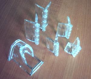
I need to get the door to open (otherwise the safe will be a little too safe…) so hinges will be needed. As the case is to be made from clear acrylic it would be nice if the hings matched.
It would be quite elegant if the hinge could be part of the door itself though. After a discussion with Dean I have decided to use a tab on the top left hand and bottom left hand corners of the door, corresponding to two holes in the case to act a pivots, testing to come in my next post.
Components:
After putting the circuit together I can see that there are no spare pins to add in new sounders or lights (humph) I can exchange the bi-colour LED for one green and one red by wiring both to the same point in the PCB. The Bi colour LED works by lighting up red when the current runs through it in one direction and green when it reverses. With the red wired anode to anode and cathode to cathode and with the green wired the opposite way round it should work in the same way.
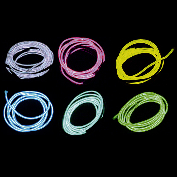
I did find a really cool component that I would have loved to use (and still might in another project) called EL wire (electroluminesent wire). It’s a thin copper wire coated in a phospher that glows when alternating current is passed through it. it’s flexible and can be run off battery or mains power.


