OK, the finished product, wow it’s taken a lot to get here and I wasn’t wrong when I referred to it as a yellow brick road, at some points in this process it really has felt like I’d been whisked off to OZ…
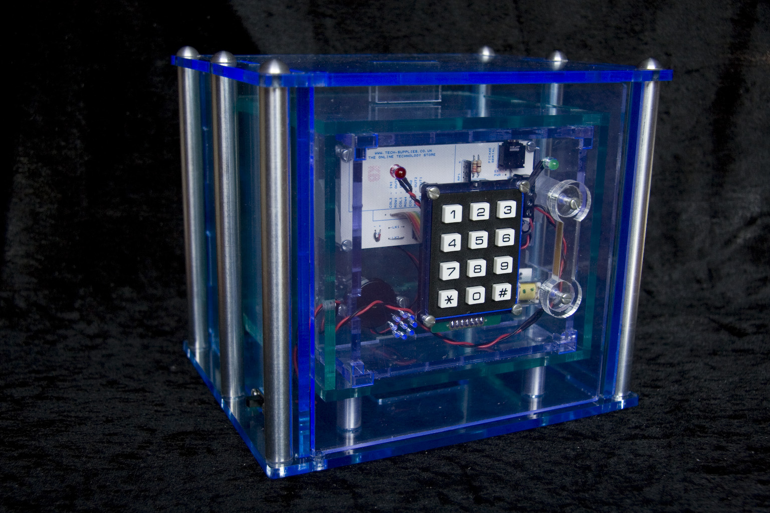
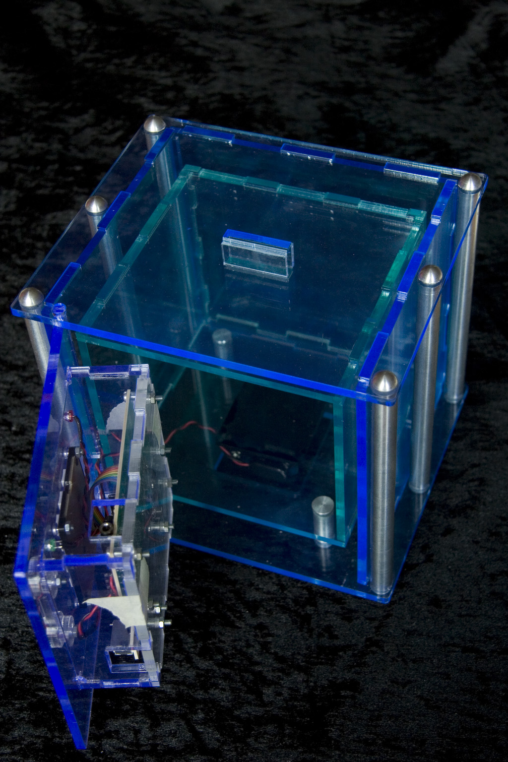
The case has come out better than I had hoped for with the 3 colours of acrylic being easily visible from the front of the safe. Something I had been a little worried about was the blue and purple of the outer components overpowering the green inner box.. My decision to use 5mm acrylic was borne out, after my initial hassle of getting the laser cutter settings right so it would actually cut through it has really added to the strength, the tabs worked as expected to support the structure and make testing easy as (with the aid of a little tape) it held itself together. One of my major successes is that 2D Design is no longer a hideous, time consuming, incomprehensible programme. In developing my ideas and producing my working drawings it has become invaluable, enabling me to work with a high level of accuracy and greater attention to detail. I love the contrast between the clear, coloured acrylic and the aluminium bar, it gives the futuristic, high-tech look and feel I have been aiming for throughout.
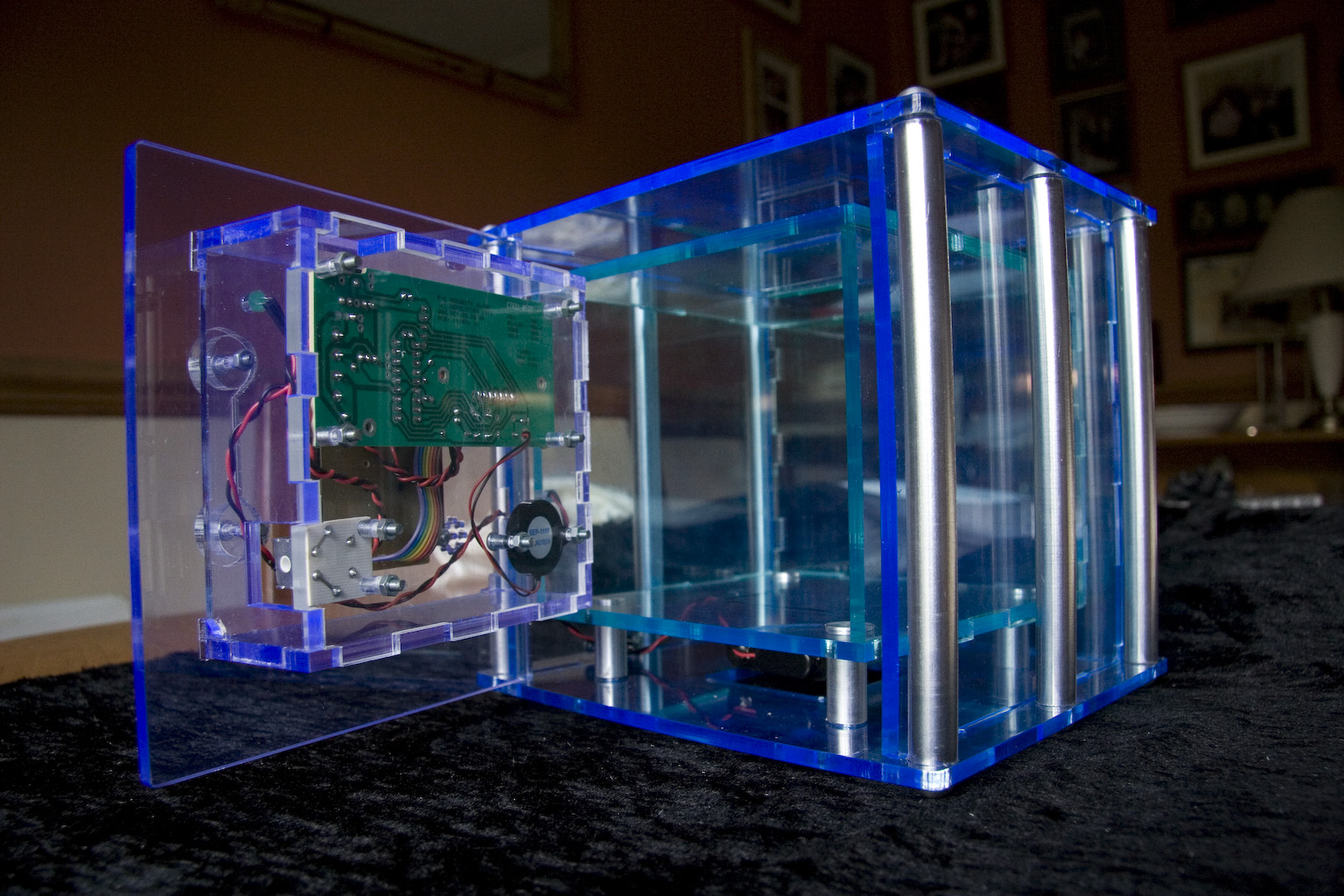
Producing the initial circuit board with the 8 pin chip really helped me to understand the work behind the kit board that I purchased. I gained an understanding of the manufacture of PCBs, the placement of components and the flow of current around a circuit. My research into microcontrollers was extremely useful, understanding what goes on inside those little black boxes makes it easier to see how you can create something from them. I have gained confidence in adding/altering components for example; exchanging the single bi-colour LED for two single colours in a way that allows them to light up in the correct manner. I have a much greater self-belief in my ability to solder, my kit worked first time and only had one problem with a static shock. I would have liked to upgrade to a bigger chip, created my own board and added more components as I stated in my specification.
One aspect I have felt confident about from the beginning has turned out to be a bit of a pain and not due to my knowledge (or lack of). I have a good understanding of basic code as well as using flow diagrams so I was able to read and understand the basic programme for my keypad and understand where to change it to get the effect needed. I believe that the alterations I made to the keypad programme would work if I upgraded my PIC chip to one with a larger memory. It was a matter of poor time manegement that led to this problem, if I had tested it earlier rather than assuming that I would have no issues I would have had enough time to upgrade my chip. I have left the back panel of the door compartment open as I want to be able to change the chip and use my altered programme.
The locking mechanism is possibly the biggest failure of this project, the main issue again was not giving myself enough time. I had assumed that as this safe needed a lock the lock had to be located within the door. if I had checked the stroke length and bought a solenoid that would cover the distance required by my clearance plan this would not have been a problem. As it was once I had constructed the box I found that it would not work due to either the bolt not reaching accross the gap or intersecting with the closing door if I moved it close enough to perform it’s required function, it was too late to change. After starting to write this evaluation I have worked out how I could arrange it so that the solenoid I have could lock the door. If I moved the solenoid to the underside of the green box, running the connecting wires along the notch and hole with the battery cable, and cutting a port for it to sit against the underside of the inner box, the stroke length would not be an issue. The door only sits 2mm above the inner box so a recess cut in the bottom of the door would catch and hold the end of the bolt. I’m hoping that by leaving the back of the door compartment unstuck I will have a chance to move it, cutting the port in the green box may be awkward now that it is fixed in place but I will persevere!
So in conclusion, does my safe answer the brief and specification I set out for it at the beginning of this process? First the successes; I am happy to state that my product would be a good candidate for batch production, all of the component parts of the case can be manufactured via CNC machinery and are simple to slot together, the combination of the 5mm acrylic and the 12mm aluminium bars have made the product very sturdy. I have carried the high-tech look and feel through to the final product and I feel that the combination of colours, materials and the design would appeal to my target audience. I have explored areas in my subject audit by experimenting with 2D and 3D modeling programmes, manufacturing using CAD/CAM, utilising 2 materials that I had not previously worked with and have created an e-portfolio, funnily enough, one of the biggest challenges of this project. Now the failures; I have managed to produce a toy safe using the keypad kit but I suppose for it to really be called a safe it needs to be able to lock! I was unable to alter my programme beyond extending the time that the lock stays open, both issues I plan on rectifying in the next couple of weeks. I added in the two single colour LEDs to replace the bi-colour one but I would really have liked to add in other sounders and lights, in my next project I will endeavour to create my own board so I can have greater control over the components I can fit. This has been an interesting journey for me so far but I think I still have a long way to go before I arrive at the emerald castle…