The first step is to find out why digital electronics are different for any other type, what makes it different? The defining point is the signals involved…
An electrical signal is a pattern over time of electrical current, there are two types of signal: digital and analogue. As you can tell by the name digital electronics is concerned with digital signals, but what is the difference between the two?
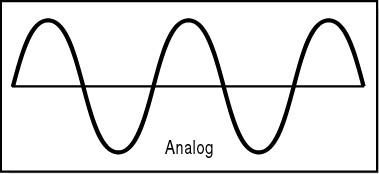
Analogue – analogue signals are a continuous electrical signals that constantly change in response to changes in sound, light, heat, position, pressure etc. it’s a one-to-one mapping of the physical quality it represents. An analogue signal will travel up and down a range of voltages, on a graph the signal could look something like this:

So analogue signals are continuous and continually varying, an analogue circuit is a circuit where the current or voltage will vary to match up with the information being represented e.g the input of an LDR (light dependant resistor). As the LDR is exposed to rising light levels the resistance of the component decreases allowing more current to flow through the circuit, the current changes gradually in response to the light levels.
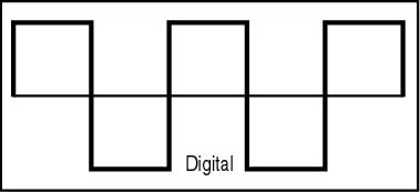
Digital – a digital signal only has two states; on or off represented by the binary digits 1 and 0 (oh boy, binary, this looks like this will be another area I need to investigate). One voltage is assigned to represent the ’1′ and another voltage (usually near 0V) to represent the ’0′. A digital signal is made by sampling an analogue signal at regular intervals and converting each value into a ’1′ or a ’0′, making a string of binary digits or bits. On a graph a digital signal would look very square (a bit like castle walls, great we’re back in the realms of my dragon slaying metaphor… realms!! I’m doing it again!):
So instead of the example above of the LDR creating an analogue signal, a digital circuit would be like having a switch in front of a bulb, the signal is ’0′ if the switch is off and ’1′ if the switch is on.
Now I have my definintion I need to work out how this signal is used…

