Now we get to have a little fun…
I’m going to take a look at the 3 types of circuit you can make with a 555 timer, astable, monostable and bistable.
Monostable – one stable state
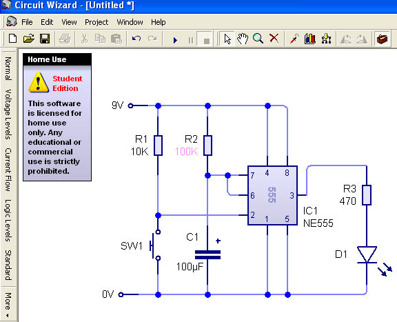
This is my monostable circuit and I’ve calculated that I need a 100K resistor with my 100µf capacitor to give me a time of 10 seconds…
Taking into account the tolerances of the resistor and the capacitor that’s pretty good going. If I wanted to get exactly 10 seconds I could use a POT or a variable capacitor.
Here you can see the capacitor charging using a multimeter (more on those here):
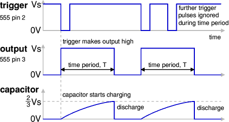
So a monostable circuit generates a single pulse when triggered, without the trigger the circuit produces a low (zero) voltage which is it’s stable state. I pulled this brilliant diagram from a site that’s been really helpful, it shows the wave forms of the signals involved in this circuit:
(http://www.kpsec.freeuk.com/555timer.htm#monostable site accessed 18/03/11)
I had one problem with this circuit in that my LED output kept burning out after 3 or 4 triggers so I decided to investigate…
My multimeter showed that 6.5 v was getting through to my poor little LED, it shouldn’t get more than 1.7V so my resistor was really not limiting enough of the current.
Using Ohms law I worked out which resistor would be best:
R = (VS-VL)/I
VS – supply voltage
VL – LED voltage
R = (6.5V-1.7V)/2ma
R = 4.8/0.02
R = 240R
So by adding another 240R to my 470R resistor I should have enough resistance to stop the burnout. As there isn’t a resistor with a value of 710R I used the next highest value which is 750R.
Monostable circuits are often used to trigger digital logic devices. Mechanical switches can ‘bounce’ when they are closed, causing voltage spikes that would confuse an IC into thinking it’s gotten a high signal. By putting a monostable in between your mechanical switch and your end device you can stop confusing signals.
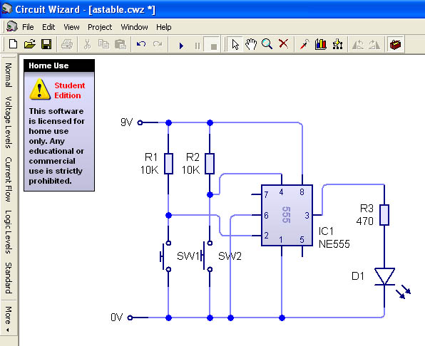
Astable – no stable state
An astable circuit is sort of like an electronic metronome using a combination of two resistors and a capacitor you can configure your circuit so you output, say an LED, will turn on and off at a set frequency. It has no stable state because it keeps changing on its own.
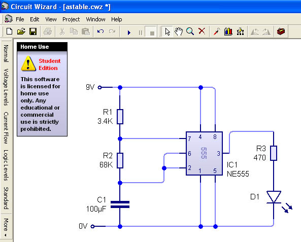
I wanted to make my output LED blink on and off for 5 seconds each, 5 on and 5 off. To do this I needed an (initially) scary range of calculations.
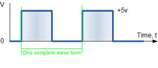
The first is for working out the frequency of your circuit, this is how many times per second your circuit completes one cycle of it’s wave form:
Frequency is measured in Hertz so a frequency of 2Hz would mean that your circuit would complete its wave form twice per second.
The next two are for working out the high (on) and low (off) times:
T high = 0.69(R1+R2)xC
T low = 0.69(R2xC)
So… you start by working out the resistor needed for the low time first:
T low = 0.69(R2xC)
5sec = 0.69(R2x100µf)
R2 = 5/0.69×0.0001
R2 = 72,464 or 72K (I tried it with a 68K)
Then you can work out R1:
T high = 0.69(R1+R2)xC
5sec = 0.69(R1+75K)x100µf
R1 = 5/(0.69×0.0001)-68,000
R1 = 4,464K (I used a 3K4)
So…
And here it is in test:
Note (25/03/11) Cool siren effect using two astable circuits and POTs! I think I’ve just made a device for communicating with dolphins… or for just really annoying dogs…
The effect of using two astable circuits feeding into the speaker and controllable from the two potentiometers gives you an enormous range of (really annoying ;)) sounds:
Bistable
Right, we’ve had one stable state, no stable states and now… yes you guessed it two stable states!
If this sounds a little like theintro to a cheap game show then I’m setting the right tone…
A bistable state circuit can be used as the buzzer system on a quiz show. The contestants each have one trigger, to trigger the high state and the quiz master has the other to reset it.
This one is the easiest one by far as there are no resistor values to calculate!!
Note (25/03/11) Mnemonic for remembering resister colours:
