One thing you can’t get away from when investigating digital circuits is logic.
I already had a vague inkling of what logic and logic gates were when I started this investigation but boy did I underestimate the scope! Here’s what I found out…
Digital circuits are made up of digital switches called gates or logic gates, a logic gate is a cool little circuit designed to accept and generate voltage signals that correspond to binary 1s and 0s. If you use lots of gates together they can be used for binary number storage (memory circuits) or manipulation (computing circuits), each gate’s output can represent one bit (binary digit) of a larger binary number (again with the binary, I won’t be able to put this off for much longer…).
Logic gates process the two state signals I wrote about in my previous post, these can represent just about any two-state or binary thing: a light switching on or off, password accepted or denied, DVD laser pit or an absence of one. By assigning logical values of 1 and 0 to the two sides of these events you can use these bits to carry information about stuff that’s happening in the real world and use them to control other things by processing them in a digital circuit.
Logical 1 and 0 can also be called true and false or high and low (like when looking at the programming of a PIC chip, high means on and low means off). Typical voltage levels used to represent these two states are 5V for logical 1 (high) and 0V for logical 0 (low) these voltages are controlled and passed on by transistors which I’ll go into later.
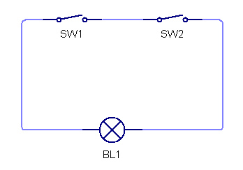
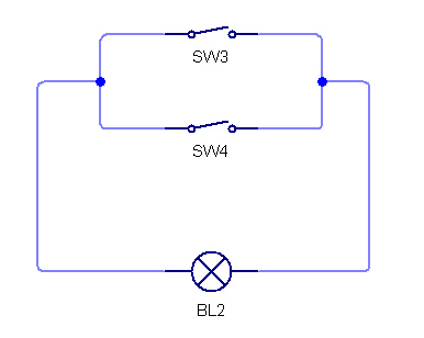
There are quite a few different logic gates but they are all made up of a combination of the 3 most simple ones; the AND, OR and NOT gates. To get a really good idea of what the AND and OR gates can do you can represent the circuits mechanically:
An AND gate can be made by connecting two switches and a bulb in series, in this circuit the bulb will only turn on once both A AND B have been switched on.
An OR gate can be made by connecting connecting the switches in parallel, in this circuit the bulb will be lit if either A OR B is switched on.
A electronic logic gates work just like this but use lots of transistors, diodes and resistors arranged in just the right way so when you apply certain input voltages you get the correct output voltage.
Logic Gates and Truth Tables
I’ve already mentioned the 3 simplest gates so now I’ll go into a bit more detail…
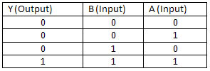
A single digital signal can be either on or off but if you start adding more signals you can get more combinations, e.g. with 2 signals there can be 4 possible outcomes, when these combinations are processed using the logic gates rules (AND, OR, NOT) each combination will have a different outcome. To keep track of these inputs and outcomes we can use a tool called the truth table, you list the various combinations of inputs in one column and, using the rule of the gate in question, work out each possible outcome.
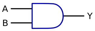
AND Gate
You can see that the truth table shows that when using an AND gate the out put will only go high when both inputs are high (a symbol is used to represent logic gates as to recreate the arrangement of components that go into one each time would be time consuming and use up loads of space).
Here are the symbols and tables for the rest of the gates I have investigated:
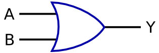
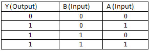
OR Gate
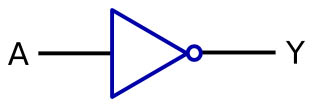
NOT Gate
A not gate can also be called an inverter, what ever input goes into is is reversed as it comes out of it, the little dot on the end of the triangle represents this inversion. You’ll recognise this in the next couple of gates…
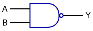
NAND Gate
This looks just like and AND gate but with the little dot of the NOT gate, this means that this gate works as an AND gate but that the output signal will be inverted, so it’s called a NOT AND or a NAND, you can see that it is the exact opposit of the results for the AND gate above.
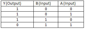
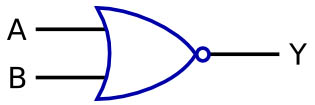
NOR Gate
This gate is just like the one above but it’s based around an OR gate, again the contents of the truth table are the exact opposite of the OR gate so this is a NOT OR gate or a NOR gate.
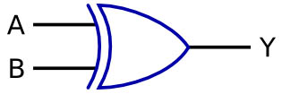
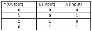
XOR Gate
The X in the name of this gate stands for exclusive so this is an exclusive OR gate. All this means is that the gate will only give a high output if only one or the other of the inputs are high, if both are high the input will be low.
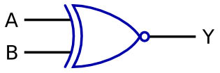
XNOR Gate
I think by this point you don’t need me to tell you how to work this one out… you do? Ok then. That symbol shows that it’s an OR gate, the curved line at the back shows that it’s exclusive and the little dot at the end shows that it’s inverted, so… an X NOT OR gate or a XNOR!
Now that I know what they are, what are they used for?
An application for an AND gate might be a gas fired central heating system. You set a temperature that you want your house to stay at, one input of the gate would be a temperature sensor in the house, the other would be a temperature sensor to indicate that the pilot light is on. When the room sensor detects a temperature below your settings it triggers a high signal to the logic gate, if the signal from the pilot light is also high (indicating that the pilot light is lit) then the logic gate can pass on a high signal to the output, namely the gas valve in the boiler. You can see the system will only work if both inputs are high.
An OR gate might be used in a burglar alarm, the inputs could be sensors in the door frame and the window glass and the output would be an alarm, if one OR the other is disturbed the alarm would sound.
These are two very simple uses for logic gates, they are also used for computing processes, these consist of lots and lots of logic gates arranged in very specific ways to give an outcome, like detecting which keys have been pressed on a keyboard (thinking about this while typing is odd, like your actually really aware for the first time of the complex processes that go on just by typing a word like and). Without digital logic we wouldn’t have devices such as computers, mobile phones and even calculators.
Phew! looking at all those ones and zeros has made me see double (ha, ha, double, did you see what I did there… no? oh well) I think this would be a good time to delve into the wonderful (and totally terrifying (at the moment at least)) world of binary code.
